Agnus

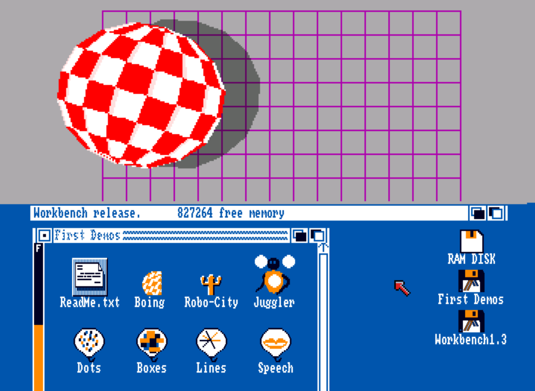
The name Agnus is derived from ‘Address GeNerator UnitS’ since it houses all address/pointer registers and controls memory access of the custom chips. So, Agnus is the central part of the Amiga OCS and ECS chipsets.

The way AGNUS does that resembles a set of traffic lights – similarly, AGNUS arbitrates the flow of data along 25 separate lanes (25 DMA or Direct Memory Access channels) within the chipset. It also provides video timings.
In its “fat” incarnations, it does more (see below).

AGNUS also contains the blitter and copper “coprocessors”:

The “Blitter” is dedicated to copying the contents of one section of Chip memory to another place in Chip memory, much faster (approx. twice as fast) than could be done with the 68000 CPU. Aside from simple copying, it can provide further manipulations: logical combining of up to 3 sources, pixel-precision shifting, line drawing and simple area filling.

The “Copper” remains synchronized with the video beam position counters (it has direct access to them without requiring any chip-RAM data transfers). It can WAIT until a specific position is reached and then MOVE some value into a chipset hardware register. A 3rd SKIP copper instruction can aid in the construction of simple IF-THEN clauses. Despite its apparent simplicity, the Copper is suited to many tasks: from simple register refreshing/reloading to perfectly controlled mid-screen colour and resolution changes to even starting the blitter in a beam-synchronised fashion.

AGNUS had many revisions made to it from 1984 until it was replaced by the Alice chip in the AGA chipset in 1992. The Agnus hierarchy generally has two main branches, the “thin” Agnus and the “fat” Agnus.

The “thin” Agnus is the original 48-pin DIP package Agnus as used in the Amiga 1000 and early “german” Amiga 2000-A (which is Amiga 1000 based). There are only two variants of the “thin” Agnus:
– 8361 (NTSC timings)
– 8367 (PAL timings)
The thin Agnus has 18-bit DMA pointer registers (to the system these appear as 19-bit, with the LSB ignored and always considered 0) and can therefore address 2^18 = 262144 words (2^19 bytes), or 512 Kbytes of RAM (the so-called chip RAM). It also has a small blitter “bug” (*), corrected in the “fat” versions.

The “fat” Agnus is the more well-known 84-pin PLCC package version, debuting in the Amiga 500 and also used on the Amiga 2000-B and Amiga 3000 systems, as well as the CDTV.  Later revisions of the “Fat” Agnus used in all the other Amiga models, other than the AGA Chipset machines.  The term “fat” is because now it integrates a simple clock generator that produces all the necessary system clocks from the master 28 MHz oscillator, and also a DRAM controller for chip/slow RAM.

Variants of the “fat” Agnus include:

– The original 8370 (NTSC) / 8371 (PAL) “fat” Agnus. Can control 1 MB of RAM, but DMA pointers are still 18-bit so only 512 KB chip RAM is supported (if present, the other 512 KB is typically mapped as $C00000 slow RAM).
Typically found on: Amiga 500 rev3 and rev5, Amiga 2000-B rev 4.x (US models), but can be found on very early rev6 Amiga 500 and Amiga 2000-B‘s as well (those boards also have a “refresh fix” additional small PCB).

– The enhanced (ECS) 8372A Agnus (model 318069-029, supports both NTSC and PAL, selectable via pin 41 at powerup and via software at anytime). Also supports additional video timings (requires the ECS Denise as well to provide these new modes). Controls still up to 1 MB of RAM but now can address all of it as chip RAM (19-bit pointers).
Unofficially called the “fatter” Agnus to signify the increased 1 MB chip RAM support.
Typically found on: Amiga 500 rev6A, Amiga 2000-B rev6.x, and the CDTV.

– The enhanced (ECS) 8372B Agnus (model 318069-03). Essentially an 8372A with 2 MB RAM support, all addressable as chip RAM (20-bit pointers). Some batches of the 8372B even use the 8372A packaging, with the B distinctly added after the 8372A part. These read like 8372AB, but internally they are 8372B parts.
Unofficially called the “obese” Agnus to signify the yet increased 2 MB chip RAM support.
Typically found on: Amiga 3000 (and also on some “megachip” 2 MB chip RAM upgrades). (**)

– The 8375 series, which are all ECS models. Some are 1 MB, some 2 MB, some are pin-compatible to the previous models, some are not. All can be software set to either PAL or NTSC but upon power up will default to their indicated variant. Most well known members of the series are:

++ 390544-01 (PAL) or -02 (NTSC), 2 MB support, not pin compatible to 8370/71/72A/72B models.
Typically found on: Rev8A(.1) Amiga 500 plus motherboards, early Amiga 600s (marked as A300), many “megachip” expansions.

++ 318069-10 (PAL) or -11 (NTSC), Vbb version of the 390544 model. 2 MB support, not pin compatible to 8370/71/72A/72B models.
Typically found on: Later Rev8A(.1) Amiga 500 plus motherboards (possible Vbb fix needed), later Amiga 600s, many “megachip” expansions.

++ 318069-16 (PAL) or -17 (NTSC). Vbb replacement to the 8372A. 1 MB support, pin compatible to the 8370/71/72A family.
Typically found on very late Amiga 2000-B systems (some require a small fix for stable operation with these chips – same when using them as a replacement to an existing 8370/71/72A).

++ 318069-18 (PAL) or 318069-19 (NTSC). Likewise, Vbb replacement to the 8372B. 2 MB support, obviously pin compatible to the 8372B model.
Typically found on very late Amiga 3000 systems. Possible Vbb “fix” needed when replacing an 8372B with its 8375 counterpart.

The AGA chipset incarnation of Agnus is the Alice chip. Both carry similar hardware and duties.

(*) Thin Agnus blitter bug: Upon instructed to begin a blit operation, the blitter will erroneously not report itself busy until it has actually fetched its first word of data. This can cause undesired behaviour. The easy solution is for the CPU to check twice if the blitter is busy – even if the 1st report is erroneous, the 2nd will always be correct.

(**) Due to limited pinout, the 8372B Agnus dumped the 2nd RAS line and replaced it by an extra mux address pin, requiring extra circuitry on the Amiga 3000 to bring back the 2nd RAS line. Interestingly enough, the Amiga 500 rev6A/7 motherboard provides all the necessary layout and jumper support for single-bank 2 MB of chip RAM using 4 1Mx4 chips and the 8372B Agnus. This feature, despite being documented, was never implemented.

Amiga 2000-A

The first “big box” Amiga, full of the new Zorro 2 expansion slots and a Video slot…  Released in 1986, this model was only produced until 1987, when it was replaced with the Amiga 2000-B.  This was the first Amiga to have Kickstart in a ROM chip, meaning that the Kickstart Disk was no longer necessary in order to use the machine, it came with the then new Kickstart 1.2.  This model is identical on the outside to the Amiga 2000-B, but on the inside we consider it different enough to have it’s own dedicated page here at The Amiga Museum.

This is the original (rev 4 – just 4, not 4.0 or 4.1 etc) Amiga 2000 mainboard, designed by a team at Commodore in Germany in 1986. About 60.000 Amiga 2000’s were sold with this mainboard.
It was soon replaced by the “cost reduced” Amiga 2000-B (rev 4.x) board, designed by Commodore US and Dave Haynie, which nonetheless preserved the original layout/form factor (positions of slots, ports, connectors etc).

Component-wise it’s very different from the US rev 4.x (which is based around the Amiga 500 rev5 design).
This one however is based upon the Amiga 1000. Actually, it’s just the Amiga 1000 and the concept Zorro II backplane add-on integrated together onto a single mainboard.
Therefore it inherits most of the Amiga 1000‘s characteristics. It uses the same “thin” Agnus chip as the Amiga 1000, so no option to upgrade to a 1 or 2 MB capable Agnus exists, it has no “Gary” chip but uses discrete logic for its functions and instead of using the Buster chip to arbitrate Zorro II access it uses a PAL-based approach.

Compared to the later Amiga 2000-B motherboards, it’s of higher quality – it uses a 4-layer PCB design vs a 2-layer design used by the US models.
Actually, part of the “cost reduced” nomenclature is due to the transition to 2-layers, the other part being higher circuitry integration in the form of dedicated chips: The functions of Gary (address decoder, bus arbiter, floppy motor control, reset), Buster (Zorro II bus arbitration) and Fat Agnus (local DRAM controller) are implemented in more expensive discrete logic in the original 2000-A, just like on the Amiga 1000.

Picture of the Amiga 2000-A mainboard (will open in a new tab).

But in other comparisons it comes short:
– ROM socket has the wrong pinout (like in Amiga 500 rev3/5) so it only takes 256 KB ROMs (Kickstart 1.2 and 1.3) without modification. It originally shipped with Kickstart 1.2.
– The CPU slot (named the MMU slot here) is limited in function compared to the US models, and typically the 68000 must be removed when a processor upgrade card is installed there, eliminating a “fallback mode” possibility.
– The video slot is also limited – no digital RGB or other signals exist there, just the ones already to be found on the external analog RGB connector. Scandoublers/flickerfixers which rely on the 12-bit RGB signals will not work.
– The Zorro II subsystem is not as stable, some cards may not coexist as well as they do on later models.
– No option for $C00000 “slow” RAM, although there is an official Commodore card for the MMU slot which provides (among other possibilities) true Fast RAM at the same $C00000 address (so it won’t conflict with the Zorro II expansion 8 MB space. The “slow” or “ranger” 512 KB RAM expansion on the Amiga 500/Amiga 2000-B was mapped to the same address to emulate this).
– No composite video out (either colour as in the Amiga 1000 or monochrome as in later Amiga 2000-Bs).
– No option to turn the audio filter off (just like in the Amiga 1000 and early rev3 Amiga 500).

Also noteworthy is that many of these (rev4 based) Amiga 2000-A systems came with a Cherry keyboard (small function keys, red Amiga keys) with a Philips MCU instead of the 657x MOS ones universally found thereafter. These keyboards typically don’t work with the PC Key (or equivalent) adapters.

CPU: Motorola 68000 @ 7.16MHz (NTSC)
Motorola 68000 @ 7.09MHz (PAL)
Chip RAM: 512K (16 256Kx1 chips onboard, non-expandable)
Fast RAM: 512K on Commodore MMU card
Maximum resolution: Hi res interlaced :768×486 (NTSC – 640×400 overscanned)
768×576 (PAL – 640×512 overscaned)
Low res non-interlaced: 384×243 (NTSC – 320×200 overscanned)
384×288 (PAL – 320×256 overscaned)
(16 colours maximum in hi-res 640x resolutions) *
Kickstart versions: 1.2
1.3 (upgrade without modification)
2.0 (with ROM jump-wiring)
3.1 (with ROM jump-wiring)
Workbench version: 1.2
1.3
2.0
2.1
3.1
Total RAM: 1024K (512 KB chip onboard + 512 KB fast on MMU card)
– MMU card supports another 512 KB of RAM, which can serve as either fast RAM or for Kickstart MapROM function.
– Up to 8 MB of Zorro-II Fast RAMMaximum RAM config: 512 KB chip + 9 MB fast (8 MB at $200000 + 1 MB at $C00000)
Price in 1986:
(US Dollars)
<- Back to Amiga 1000 On to Amiga 2000-B ->

Ron Nicholson

Ron Nicholson was one of the original designers of the Amigas AgnusDenise and Paula chips.

Joe Decuir

Joe Decuir was one of the original designers of the Amigas Agnus and Denise chips.

USA Patents granted to “Joe Decuir”, including many of the original patents for the Amiga.


The Amigas graphic modes

Perhaps the most revolutionary aspect of the Amigas unique hardware was the way the custom chips could be programmed to produce outstanding graphics output for the time.  This was certainly what the Amiga was best known for, and even today, what was possible on these machines can be quite stunning.

Some of the neat tricks that were possible included EHB, HAM, showing several different “screens” at once (each with their own resolution and colour palette), COPPER effects, Sprites, BOBs and with the AGA Chip Set in 1992, changes to the existing graphic modes (enabling higher resolutions to be used with them), and the addition of the HAM8 display mode.

EHB
Extra Half-Bright mode enabled the display of up to 64 colours, without needing to use the more complex HAM mode.  It enabled 32 selectable colours, but then automatically derived an extra 32 colours from those initial 32 that were half as bright.  This mode was not available on early versions of the DENISE chip in the Amiga 1000, but it was available on later production models of the Amiga 1000 as well as on every other Amiga machine produced.
[Insert EHB demonstration picture here]

HAM
Perhaps the most well known graphics mode of the Original Chip Set was the HAM mode, which enabled the display of up to 4096 colours at once on the screen in up to 368 x 482 (NTSC) or 368 x 580 (PAL) resolution.  This screen mode is also known as HAM6, to differentiate it from the HAM8 mode of the AGA Machines.  The way HAM6 modes work is somewhat complex.

Each colour register is 12-bit wide, with 4-bits per colour component (R, G, B). Example: 1111 0000 0000 = fully red

HAM uses 6 bits per pixel (*)

The 2 higher bits can be 00, 01, 10, 11 and act as a ‘rule’

00 = use the lower 4 bits (which represent a number between 0 and 15) as a direct index to the desired color register for this pixel. The pixel gets whatever color that register contains

01 = use the lower 4 bits to replace the previous pixel’s ‘blue’ bits, thus producing a new colour. The pixel gets this colour.

10, 11 = same thing, but for ‘red’ and ‘green’ bits of previous colour, respectively.

Since this works by holding the value of the previous colour and then modifying (part of) it, we get the Hold And Modify aka HAM term.

Now it’s obvious that under HAM we only get 16 colours which can independently be written to any pixel. All other colours will be treated as step-by-step modifications of previous colours and might take up to 3 pixels to reach the desired colour, causing annoying ‘fringing’.

Careful selection of the 16 base colours can make a tremendous difference in terms of HAM fringing for a given image.
Ideally, these 16 ‘base’ colours must be “related enough” to the image, in that they appear frequently in it, yet “distant enough” from each other, i.e. they shouldn’t have common RG, RB, BG parts at the very least.

HAM can’t be used in hi-res mode as this would still require 6 bits/pixel, while Denise maxes out at 4 bits/pixel in hi-res (and has to completely hog the chip RAM bus for those 4 bits/pixel, too).

It’s also apparent that HAM works well because, luckily, the lower bitplane bits are exactly as many (4, that is) as the bits per colour component (4, again). So we get to fully modify the component leading to full utilisation of the 4096 colour palette.

This isn’t true in HAM8, the AGA version of HAM, where the bitplanes are 8 and thus (considering the 2-bit ‘rule’) we have a 2 + 6 bit scheme,
aka 2^6 = 64 base colours (for the 00 rule) and 6-bit replacement values for the 01, 10, 11 rules.
But AGA being 24-bit uses 8 bits per colour component.
So, in effect, HAM8 wastes 2 bits per colour component (the 2 least significant ones are taken to be 00) for the equivalent of a 6 x 3 = 18-bit colour space scheme.
Still, 2^18 = 262144 colours (and with 64 base colours now which further reduces fringing with good base selection) is hardly disappointing, esp. considering it works even in 1280 x 512.
A 1280 x 512 screen contains only 655360 pixels anyway, couldn’t use more colours than that no matter what.

(*) HAM can be used with 5 bitplanes as well, but then only the 00 and 01 rules are in effect as the 6th (highest) bit is always taken as a ‘0’ so not much use in it.

All 4096 colours shown at once.

All 4096 colours shown at once.

Multiple Screens
Because of the way the Amiga Chip Set works, it was entirely possible to have, say the top half of the screen showing a HAM display, and then have the bottom half of the screen showing in a higher resolution with less colours.  In fact, the Amiga Workbench Operating enviroment was designed to take full advantage of this feature, enabling the Workbench screen to be dragged down at any time by the user using the mouse to reveal any screen that may have been opened behind it.  This meant that if you wished to do so, you could have Deluxe Paint, Workbench, and a text editor all running at the same time, all on their own screen, and you could switch between each screen instantly, or pull one down to reveal another behind it, so you could see more than one screen at once.
This functionality could also be used in game software, so for example, at the top of the screen you could have your score in high resolution, while the main game screen could be low resolution in order to display more colours.

The famous BOING demo, behind Workbench 1.3

The famous BOING demo, behind Workbench 1.3

COPPER effects
The COPPER is a part of the AGNUS Chip in the OCS and ECS machines, and within ALICE in the AGA machines.  It is a very simple processor that is syncronised with the display output from the DENISE (OCS and ECS) or Lisa (AGA) Display chip.  It is able to change the data going to the display chip according to a simple program often known as a display list.  This is what enables the multiple screen fuctionality, and can very easily be set to change the colour registers as the display is built, enabling for example, the background colour to change with each scan line, thus enabling a beautiful background clour effect using well over 200 colours without the need to resort to using EHB or HAM, or in fact in conjunction with these modes.
[Insert Copper effect demonstration picture here]

Sprites
Like the Commodore 64 did before it, the Amiga can display hardware sprites.  On OCS and ECS machines, Sprites are limited to being 16 pixels wide and up to 3 colours (with a 4th ‘colour’ being transparent), although they can be any number of lines tall.  You can get the illusion of more colours by using more than one sprite at the one location on screen, as each sprite can have it’s own 3 colours.  There are a total of 8 Sprites available, although it is possible to re-use a sprite at a different point further up or down on the screen, as long as they do not overlap – you cannot use more than 8 sprites on a scanline.  Due to Sprite and screen bitmap sharing the same DMA, the more overscan used (widening the available screen resolution from say 320 pixels wide to say 368) with reduce the number of sprites available to use – although sprite #0 will always be available.

BOBs
Blitter OBjects (BOBs for short) are much like Sprites, but they are objects drawn by the Amigas Blitter (Part of the AGNUS or ALICE Chip) into the existing screen bitmap, so unlike sprites they are not independent of the screen colours and resolution, but more than 8 can be used on a single scan line, and they can use as many colours as the screen mode chosen allows.

Changes to existing Graphic modes with AGA
The changes made to the Amigas custom chips for the AGA Chipset were changes to the display system, as eluded to in the name – Advanced Graphics Architecture.  This enabled the display of EHB and HAM modes in all available screen resolutions, and enables up to 256 colours without needing to use the copper or HAM mode.  Sprites could also now be displayed in hires and superhires vertical resolutions, and can now be 32 pixels wide, instead of the 16 pixel width limitation of the OCS and ECS chipsets.

HAM8
The AGA Chipset brought 24-bit wide colour registers, with 8-bits (256 levels) per colour component (R, G, B). Example: 00001111 11111111 00000011 = red 015, green 255, blue 003

This allows for a true-colour palette: 256x256x256 = 16777216 available colours, compared to the OCS/ECS 12-bit (16 levels per colour component) palette: 16x16x16 = 4096 colours.

The AGA chipset also brought the capability to handle 8 bitplanes, even in 1280 pixels super hi-res modes.
Thus a new HAM mode was added, appropriately named HAM8, as it makes use of 8 bitplanes compared to the 6 bitplanes of the traditional OCS/ECS HAM6 mode, while utilising the same hold-and-modify principle.

As explained in the HAM6 section above, HAM8 can’t make full use of the 16777216 colour palette since of the 8 bits, 2 must be used for the ‘rule’, so it can only modify 6 of the 8 bits of a colour component for each pixel. This effectively produces 2^6 = 64 levels for each component, giving an 64x64x64 = 262144 ‘usable colours’ HAM8 palette.

But, since the base palette is extended to 64 colours in HAM8, if it is chosen well, it is almost impossible to tell the difference between a picture being displayed in true-colour mode on a modern computer, and a picture being displayed in the same resolution HAM8 mode on an Amiga 4000/1200/CD32. This almost-true-colour capability was something unheard of for a home computer at the time the A1200 was launched.

For more examples of what could be done on the Amiga, and exactly how it was done, this is a fantastic site to explore: http://codetapper.com/amiga/sprite-tricks/agony/

Chip and Fast RAM

What is Chip RAM?

Chip RAM is RAM that can be accessed by the Amiga Agnus or Alice chip, as well as by the Central Processing Unit.  It is where the sound samples that are played by Paula are stored, it is where the data that makes up the display is stored.  The contents of Chip RAM can be read and written by both the CPU and the custom chips (via DMA access with the Agnus or Alice chip), however while it’s being accessed by one, it can’t be accessed by the other, the custom chips have priority over the CPU.  This means that if there is only Chip RAM in a system, there will be times when the CPU has to wait to access it, slowing down the systems CPU.

What is Fast RAM?

Fast RAM does not have the limitation mentioned above, but it can’t be accessed by Agnus or Alice, it can only be addressed by the CPU.  Thus, simply adding Fast RAM to any Amiga that only has Chip RAM can potentially speed up the machine.

Alice

The Alice custom chip.

Alice was the replacement for the Agnus chip in the AGA revision of the Amiga custom chipset.

Denise

DENISE is a contrived contraction of Display ENabler.

In the early days of the Amiga 1000 and Amiga 500, it was often called Daphne. There is no functional difference, aside from the revision used in early Amiga 1000s (8362 R5, typically a ceramic package) being unable to display the EHB graphic mode.

In the OCS and ECS machines, DENISE uses up to 6 bitplane data registers to get the display data that AGNUS (via its corresponding DMA channels) retrieves from chip RAM.

The bitplane data, in relation with the currently enabled graphics mode, result in a constant stream of 12-bit digital RGB output values (4 bits per Red, Green, Blue components) synced to the display mode. The digital data is then fed into a resistor network known as the Video Hybrid (or VIDIOT) which produces the final analogue RGB signal, still synced to the display mode, now ready for display on a TV screen or monitor.

DENISE also reads in (in multiplexed form) the axis information from both mouse ports.

It is also responsible for displaying any sprites being used, using up to 8 sprite data registers fed at the beginning of each scanline through Agnus’s corresponding sprite DMA channels BEFORE any bitplane data is read.

Furthermore, it handles the relative priorities between the display playfields and the sprites and can detect specific sprite/playfield collisions thus assisting in games design.

DENISE was replaced by the LISA Chip in the AGA Chipset (the only truly 32-bit component of the AGA chipset).

DENISE received a fully pin-compatible revision update, 8373 R4 (by default found in Amiga 3000, Amiga 500Plus, some late Amiga 2000s, Amiga 600) known as “Super DENISE” to differentiate it from the original chip.
Along with an ECS Agnus, it’s part of the ECS chipset.

These later versions of DENISE were capable of a greater range of screen display resolutions and scan rates, but also require an ECS Agnus (can be either a 1 MB of 2 MB version) to provide the necessary timings for the new display modes.
So it’s quite possible to “convert” any older A500/A2000 to ECS specs, the exceptions being the A1000 and the early “german” A2000, which use the “thin” 48-pin DIP Agnus variant instead of the “fat” 84-pin PLCC one. An ECS Denise can of course still be installed, but will behave as an OCS one.

The new display modes depart from the original NTSC/PAL-timed only modes (60/50 Hz, 15.7 KHz) and can use newer VGA-style displays, but since the default modes were still the original ones, this was practically only useful to owners of dual-scan or true multi-scan displays (such as the dual-scan Commodore 1940/1942 models).

Availability of such monitors had always been limited as only the ancient CGA and the already surpassed EGA modes used less than 31 KHz in the PC world. By 1991 VGA was the de facto standard and there wasn’t much reason for PC-oriented monitor manufacturers to support anything else.
This was partially solved with the availability of internal/external scandoublers/flickerfixers, which allowed the original modes to display on such monitors.

The Amiga 3000 models already came with a scandoubler/flickerfixer onboard. The same hardware (Amber chip based) was sold by Commodore as a separate video-slot card, the A2320 display enhancer, but as it supports 12-bit colour depth it was really suitable for the A2000 only.

A number of third-party scandoublers/flickerfixers for AGA-based Amigas were made, but some support 18-bit depth (262144 colours) instead of the full 24-bit (16777216 colours) AGA is capable of, and should be tested with a 256-level grayscale pattern to reveal such limitations (if relevant info is unknown or not clear enough).


The ECS Chipset…

The Enhanced Chip Set (ECS) was an incremental update to the original chipset (OCS), increasing screen resolution options when both AGNUS and DENISE chips are the ECS versions.  It also allows software switching between the PAL and NTSC video standards.

The Amiga 3000 was the first machine to be available with the full ECS chipset, allowing higher resolution graphical output, as well as much more flexible options for video output.

It consists of upgrades to the AGNUS chip  and the DENISE chip, while the rest of the system remained much the same.

Some machines, such as the Amiga 2000 and Amiga 500, came with the ECS version of the AGNUS chip, but with the OCS version of the DENISE Chip.  Upgrading the DENISE Chip in these machines upgrades the machine to the full ECS specification and allows the higher resolutions and PAL/NTSC software switching functionality.  Older machines that came with the OCS AGNUS chip, would require both the AGNUS and DENISE to be upgraded in order to gain the improvements in ECS, this was not always possible, as the Amiga 1000 and Amiga 2000-A machines  had different sockets for the AGNUS chip – for more information please see the AGNUS page.

ECS was intended to be backwards compatible with the original chipset, however some software that made use of undocumented features was not compatible.  This was mainly game and demo software.

The OCS Chipset…

The Original Chipset

The original Amiga chipset was used in the original Amiga 1000, the Amiga 2000-A and Amiga 2000-B, the Amiga 500 and the CDTV.  In 1990, the Amiga 3000 featured the ECS chipset, which was an update of the Agnus and Denise chips, and some of the chips in the Amiga 2000-B and Amiga 500 were updated with some of the ECS chips.  In 1992, Agnus and Denise were were replaced by Alice and Lisa in the AGA Chipset.  The Paula chip, which was one of the original chips in the original chipset, remained functionally similar in all versions of the Amiga machines.

What was revolutionary about the Amiga chipset was that each chip worked independently of each other and of the central processor and could be programmed.  Thus sound could be played, the display could be changed, and the central processor was still free to do whatever work necessary.  This means that the central processor didn’t need to be as fast as in competing systems, where the central processor had to do the work that the Amigas custom chips did.

Paula was the name given to the Audio chip, which also handled the floppy disk drives and the serial port.  Paula was essentially unchanged for the entire lifespan of the Amiga, and was found inside every single model Amiga.  More information on Paula can be found here: The Paula Chip.

Denise was the main video output chip in the OCS Chipset.  Denise read in the data from Chip RAM for the display and used that to determine what would be shown on the screen. Very early Amiga 1000s had a different Denise chip to later Amiga 1000s and all later Amigas that was not able to display the Extra HalfBright 64 colour mode, which worked on all later revisions.  More information on Denise can be found here: The Denise Chip.

Agnus was the heart of the Amiga chipset, and was in charge of interfacing the other custom chips with the “Chip RAM“, amongst many other tasks.  More information on Agnus can be found here: The Agnus Chip.

A picture in the HAM (Hold And Modify) mode, capable of showing all 4096 colours at once on screen.  This could be shown on an Amiga 1000 from 1985!


Next Page »